Blog #7

Blog #7

Team: “Veggie Sticks”

Project Updates

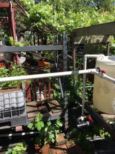
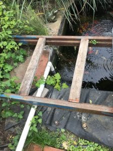
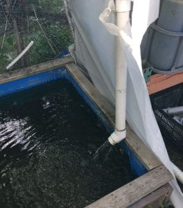
Installation is ALMOST DONE!! The installation was set back slightly due to the amount of additional work that was required to clear the area and move the plant beds around. First, the barrel needed some final modifications for it to be ready for the piping swap. A two inch diameter hole was made in the side of the barrel to serve as the clean water output. This was sealed with a rubber gasket to prevent any chance of leaks. Next, the swirl filter was put into place, and the piping was connected to the output of the fish pond pump. Various length of pipe were cut and mended in order to make this work. Finally, the piping for the output of the barrel was installed. Thanks to our own PVC specialist and Pipe Master, Aaron, this process went on without a hitch! In the picture below, you can see the new piping set up. The vertical section of pipe on the left hand side enters through the top of the barrel. This is where the water is pumped in directly from the fish pond.
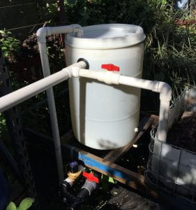
The horizontal lengths of pipe that leave from the gasket on the barrel are what direct the clean water to the plant beds. This is split into two pipes here, one going to the bed directly next to the tank and the other pipe takes it to the other plant beds and deep water culture beds. Below is a picture of the water outlet into the deep water culture beds.

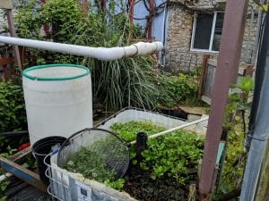
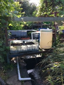
This type of grow bed is better suited for leafy plants like lettuce and kale, which grow at an even faster rate with this method. Currently there are lettuces growing (not pictured) in the deep water culture beds. Below are a couple pictures of the entire system so far. You can easily see where the outputs of the barrel go, as well as the usefulness of the opaque barrel.

The previous barrel was solid blue, which did not allow users to see the water level or the waste accumulation in the bottom. In the picture, you can see clearly where the water level is and the absence of sediment at the bottom of the barrel.

Next Steps

We are going into the final week! The piping from the waste output of the barrel will be connected to the biogas unit, along with the electronics. The area has been cleared of weeds and debri that were originally blocking the path from the output valve to the biogas unit, which will make installation a breeze. We also include two educational posters. One will be placed on or near the barrel, illustrating how the barrel works. The second will be placed on the biogas unit, illustrating how biogas is produced and what the inputs are. After that, the project will be COMPLETE!!
Blog #6

Blog #6

Team: “Veggie Sticks”

Project Updates

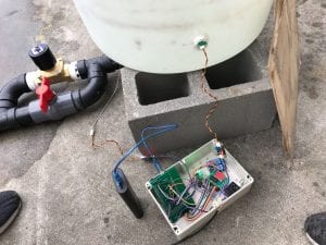
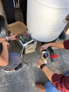
The end is NEAR!!  Installation has begun at Middlebrook Community Garden. Final touches have been made on the waterproof box for the electronic and the user manuals are in the works! The barrel has been installed and filled with water to test the supports that will be holding it, as well as testing the waterproof seals around the turbidity sensors. After over a week there have not been any leaks and the supports are clearly intact, as expected. Below is a picture of the barrel placement at the garden.The placement of the new barrel is lower than the original, by 10 inches, this will decrease the pump head which in return will increase the efficiency of the system. We originally wanted to increase the height of the barrel to ensure that the flushing function of the barrel would have enough pressure to reach the biogas unit. After talking with an aquaponic specialist who helps out at the garden, we discovered that the height of the surface of the water is what needs to be higher than the biogas unit. This was incredibly useful information, one that can also be proven with fluid dynamics calculations which will be included in our final report. Below is a picture of the original barrel and its elevated platform. You can also see the abundance of vegetation that has been growing! We did not take part in the planting, however, it is great to see that the system is producing beautiful vegetables!Also pictured above, on the lower left hand side of the picture, are the electronics for the project. This is the “brain” of the system. Inside the box we have the arduino and PCB which control the solenoid valve. On the PCB are three LED lights that are color coded so the user will know which value is being displayed on the digital readout. The three different values are: turbidity, pH, and temperature.

Next Steps

The barrel is in place, but we need to finalize the connections between the barrel and the biogas, and place the input from the pond into the barrel. We also need to drill one more hole in the barrel to serve as the outlet, which will drain clean water from the barrel to the plants. User manuals need to be finished and the interactive poster displays to make the project installation a learning experience will also need to be created.

Blog #5

Blog #5

Team: “Veggie Sticks”

Project Updates

The final phase of the project has begun! After the successful testing last week with placement of the turbidity sensors, we went ahead and bought “Mr. Sticky” which is an incredibly STICKY glue that can cure underwater if necessary. Holes were cut in the barrel and the turbidity sensors were tacked into place. The challenge was to make sure the adhesive did not cover the tips of the sensors, which would create false readings. Luckily we had a team member crawl into the barrel to clean off any excess glue that may have made its way onto the tips of the sensors. A picture of this fun moment can be seen below.

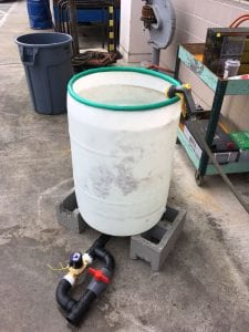
Next we needed to make sure that the newly sealed holes were not going to leak, so we filled the barrel to the top and let it sit out for a few days in the outside work-space of the engineering building. IT WAS A SUCCESS! No leaks, and the sensors fit nice and snug in the barrel. Below is a picture of the barrel filled up. The water on the ground was from testing the flushing system, not from leaks.

The next test was to determine the readings of the sensors with clean water, and contaminated water. The dirty (fish waste) water was just coffee grounds, but as mentioned in a previous blog, this mimics the fish waste almost identically. The readings are on a scale of 0-5, 5 being the most clear. The clear water read 4.8, and the “dirty” water read 1.4. . These values are what we expected, however when the coffee grounds were settling there was a lot of fluctuation of the values. Once settled the value remained at 1.4. This is something that needs to be accounted for in the code, we plan to add a timer that will only actuate the valve if the turbidity reading is below 2.0 for more than X amount of time. This value has yet to be determined. Below are pictures of the testing.

Turbidity Testing

Coffee grounds used to mimic fish waste.

We went on one last visit to the garden to take a couple more measurements and determine the placement of the barrel. We decided the place the barrel at a position that is lower than the current one, which will reduce the pump head and in return will increase the efficiency of the system. Below is a picture of where the barrel will go.

Next Steps

Finalize the installation at the garden by connecting the tank to the pond, plant beds, and biogas unit. Make sure the system still runs correctly (we are changing the height of the barrel so there may need to be some edits to the system). Complete the waterproof casing for the electronics. A box was ordered, but a hole will need to be drilled and the PCB board will need to be attached to the lid of the box for easy viewing. After these steps are completed we will make some interactive displays for the system that will help explain what we have installed!

Blog #4

Blog #4

Team: “Veggie Sticks”


Project Updates

Since our last post we met with our community partner, Alrie Middlebrook at Middlebrook Garden, and gave a presentation on what we had done and planned to do for this semester. We met with an engineer who specializes in aquaponics, and a koi specialist. Both of whom were very helpful and great knowledge banks!

After the meeting we got to work. Testing, testing, testing, and more TESTING!

Test one: Assemble the barrel with both valves (actuated valve, and manual back-up), and test for leaks. This is where we ran into the first problem. There was a small dripping leak from one of the manifolds underneath the barrel. This was only apparent after the tank was allowed to sit overnight, full of water. Luckily, this was fixed by tightening the valve, and boom! No more leaks! Below is a picture of the valve assembly.

Test two: PCB and actuated valve configuration. We wired everything up and tested the valve, and it all worked smoothly! If one turbidity sensor was blocked while the other was left uncovered, the valve stayed closed. Once both sensors were covered the valve opened, just as planned! The picture below shows the PCB connection with the valve.

Test three: Mock fish waste test! YAY! A bucket of coffee grounds was acquired from a coffee shop to mimic the solid fish waste that will settle at the bottom of the barrel. We wanted to make sure that the valve would still open and close even with a thick sludge at the bottom of the tank. This also went on without a hitch. Below you can see the bucket of coffee grounds and the “dirty water” flowing freely from the actuated valve.


Test four: This is where we ran into some issues. The turbidity sensor, by design is not waterproof, except for the very tip. Our original work-around idea was to drill into the side of the barrel and place the sensors in with bolts and a seal. This was tested on a milk jug, and water poured out, even with the bolts tightened down. Next, we thought we could waterproof the entire sensor and have them completely submerged. We attempted waterproofing the entire sensor with PVC epoxy, however, the first attempt leaked and the second filled with glue. Glad we tested this one ahead of time! Below is a picture of both failed attempts at waterproofing the sensor.

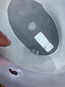
Test five: Back to the original idea. Two sensors down, we decided to go with the original idea of placing the sensor in the side of the barrel. We used a flexible glue, and did not use the two bolt fixtures on the sides of the sensors. We thought that the more we drill into the barrel, the more room for leaks. A hole was cut in the side of a plastic bucket, and the tip of the sensor was glued in place….AND IT WORKED! No leaks. We will use a much stronger plastic cement when doing this to the 55-gallon barrel, but it is great news that there weren’t any leaks even with the improper glue. Below is a picture of the sensor glued in place with the water in the tub.


Next Steps

After this round of thorough testing we can begin final construction and installation of new waste container at the garden! This coming week we will place the sensors in the barrel and test to make sure the seal is in fact, water proof. Once we have determined this, we can finalize the code with real data from the sensors. Then the tank can be installed at the garden! We also plan to include a swirl filter, which will help the waste accumulate at the bottom, which can be installed at the garden as well.

Spring Blog #3

Blog #3

Team: “Veggie Sticks”


Project Updates

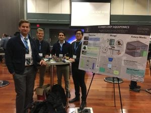
The IEEE conference is in the books! We had a great time showing off the work we have done; this was shown by our awesome poster and the sensor/actuated valve demonstration we had. People seemed to genuinely show interest in our project. One of our team members, Lok Yu, made it onto a local Chinese news station while he explained the project. The back sides of several of us also made it onto the news…which is still EXCITING! Below is a picture of our team in front of the poster we designed. The non traditional setup of the poster brought lots of attention to our group, and sparked interest in a lot of the attendees of the conference.

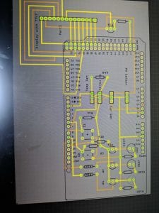
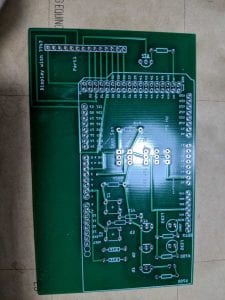
From the time of our last blog post, we have made headway on the electronic portion of the project. A schematic of the wiring was created and then sent out to a manufacturer to create a PCB that will allow us to have a much cleaner setup. Below, first is the schematic and second, the final PCB. The original prototype for the sensors and actuated valve have a chaotic wire mess, which is cleared up with the use of the new PCB.


Aside from the electronics, we have not done as much with the construction portion of the project. We plan to meet with our community partner this Monday, March 4th, and get the last needed measurements, as well as begin the testing of out barrel.

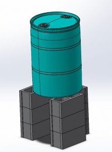
There was some debate on what we will use as a stand for the fish waste container (barrel). We were torn between creating the stand from metal or cinder blocks. We have decided to go with the cinder block option, which will allow for more variation when we install. This is also a much easier option to get the barrel testing started. Below is a CAD rendering of the proposed barrel stand using cinder blocks.


Next Steps

This coming week we will finalize the PCB board connection to the sensors and actuated valve, and begin the testing of the barrel. We plan to meet with our community partner as mentioned above, which will kick start the process.

Stay tuned for more updates!